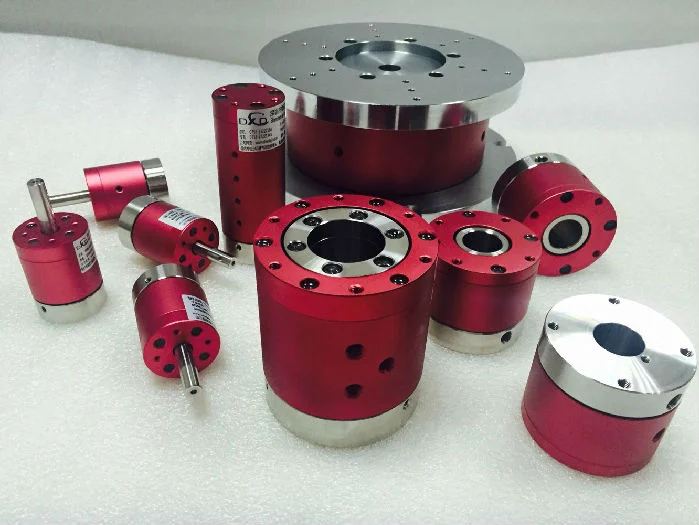
Selection of rotary joints
11Early rotary joints had relatively limited functions, mainly relying on a single pathway and only capable of transmitting one medium....
View detailsSearch the whole station
The structure of an electric slip ring is actually not complicated, with only two components at its core, with clear division of labor and seamless coordination, just like a “rotating plug and socket”:
1. Rotor (the part that rotates with the equipment)
The rotor is the “rotating end” of the electric slip ring, usually connected to the rotating components of the equipment (such as the robotic arm, fan blades, camera lens), and will rotate 360 ° along with the equipment.
There are circular conductive bodies on the rotor, which we call “conductive rings”. The material is usually copper, silver, or other metals with good conductivity and low wear rate. These conductive rings are the “transmission carriers” of current and signals,
Each conductive ring corresponds to a transmission channel (which can be understood as “an independent wire”).
2. Stator (fixed and immovable part)
The stator is the “fixed end” of the electric slip ring, usually installed on the fixed bracket of the equipment, and will not rotate with the equipment. One end is connected to the external power supply and control cabinet (i.e. the “source” of current and signal).
The stator is equipped with “electric brushes” (also known as contacts), one end of which is tightly attached to the conductive ring of the rotor, and the other end is connected to an external wire. The material of electric brushes is mostly precious metals (such as gold and silver alloys), with the aim of reducing
Wear and tear when in contact with conductive rings, reduce contact resistance, and ensure stable transmission.
Additional sentence: The contact pressure between the brushes and conductive rings of high-quality electric slip rings will be precisely adjusted, which will not cause poor contact or signal interruption due to too little pressure, nor will it wear out too quickly due to too much pressure,
Affects the service life.
Working principle: One step understanding of the core logic of “rotation without winding”
Once you understand the division of labor between the stator and rotor, the working principle becomes very easy to comprehend. The entire process is like a “rotating faucet”, which can be disassembled in three steps:
Step 1: Build a transmission path
The electric brushes of the stator are tightly attached to the conductive ring of the rotor, forming a “rotatable conductive contact point”. At this point, external currents and signals will be transmitted through wires to the brushes of the stator, and then transmitted through the brushes
To the conductive ring of the rotor – this establishes the transmission path from the fixed end to the rotating end.
Step 2: Maintain contact during rotation
When the rotating parts of the device drive the rotor to start rotating, the conductive ring on the rotor will rotate together, but the electric brush on the stator will always be fixed and tightly adhere to the surface of the conductive ring, without coming out of contact.
Here’s an analogy: you hold a chopstick (electric brush) tightly attached to a rotating plate (conductive ring), and no matter how fast the plate rotates, the contact point between the chopstick and the plate always exists. This is how the electric slip ring can continue to operate
The key to transmission.
Step 3: Stable transmission without interruption
Because the electric brush and conductive ring are always in contact, the current and signal will be transmitted continuously and smoothly through the path of “stator → electric brush → conductive ring → rotor → rotating parts”, even if the rotor rotates 360 ° or 720 °,
Even infinite rotation, transmission will not be interrupted, and there will be no problem of wire entanglement. Conversely, if it is necessary to transmit signals from rotating components (such as sensor detection signals) back to the fixed end, the same logic applies: signals are transmitted from the conductive ring of the rotor to the brushes of the stator, and then through wires
Transfer to the control cabinet.
Additional knowledge point: Why can some electric slip rings transmit multiple signals?
Many people may wonder that industrial equipment not only requires power supply, but also Ethernet transmission USB、 How to achieve simultaneous transmission of various signals such as industrial buses and electric slip rings?
The answer is simple: the conductive rings on the rotor are “independently separated”, with each ring corresponding to an independent transmission channel. Different channels are responsible for transmitting different currents or signals without interfering with each other.
For example, a conductive ring is responsible for transmitting 220V power, another ring is responsible for transmitting Ethernet signals, and another ring is responsible for transmitting sensor signals. These channels work in parallel, like multiple independent “highways”,
Each transmission corresponds to its own “vehicle” (current/signal), without congestion or interference

Early rotary joints had relatively limited functions, mainly relying on a single pathway and only capable of transmitting one medium....
View details
Sealing performance: Among the many technical indicators of rotary joints, sealing performance is undoubtedly the most critical one. In order...
View details
Textile Machinery Rotary Joint: A 'Dynamic Bridge' for Steam and Hot Water Transmission
View details
n the vast system of modern industry, heavy equipment is the main force of production, and its efficient and stable...
View details