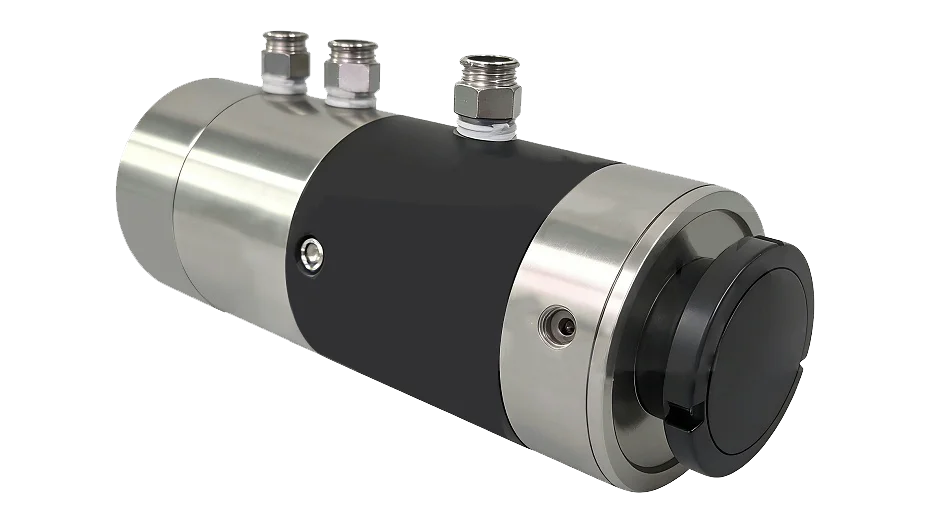
How to solve the oil leakage of the thermal oil rotary joint?
18impurities in thermal oil are one of the main causes of oil leakage in rotary joints. Therefore, before solving the...
View detailsSearch the whole station
The rotary joint should be installed correctly according to the installation and use instructions, otherwise its sealing performance and service life will not be fully utilized.
3.1 Assembly and installation of one-way rotary joints and matching equipment.
3.1.1 Connect the metal hose and transition joint (or flange) directly to the rotary joint, and use a workbench clamp to clamp the rotary joint housing during installation to prevent damage to the seal.
When the hollow shaft is connected to the rotating body using threads, a layer of white lead oil or polytetrafluoroethylene tape is generally applied to the thread, and the hollow shaft is clamped with a tool (usually designed with a wrench clamping surface) and screwed into the center of the threaded connection hole of the rotating body until it is tightened.
When the hollow shaft is connected to the rotating body using a flange, a uniformly thick washer (such as a copper washer or a PTFE washer) should be added to the end of the hollow shaft extending from the flange. Then, the mating part and screw hole of the rotating body should be aligned and fixed with bolts. When tightening the bolts, the corners should be tightened, and finally, the torque should be the same.
3.1.4 Assemble the anti rotation and load-bearing lifting structural parts of the rotary joint, and adjust the concentricity between the shell and the hollow shaft to prevent the shell from shaking or rotating during the installation and use of the rotary joint.
3.2 For the fixed rotary joint with bidirectional inner tube, the connection between the outer tube and the supporting rotating body is the same as that of the unidirectional rotary joint, except for the installation of the inner tube.
3.2.1 The connection method between the inner pipe and the end cap of the rotary joint generally adopts cone pipe thread and pipe thread connection, which is opposite to the rotation direction of the supporting rotating body and the same as the rotation direction of the outer pipe connected by thread or supporting rotating body. When the outer pipe is connected by a flange, the inner pipe and the end cap must be connected by threads, and the end of the inner pipe must be locked inside the end cap with a nut.
3.2.2 During installation, align the inner pipe from the end hole of the outer pipe to the screw hole of the rotating joint cover and tighten it. Then, send the inner pipe into the inner cavity of the rotating body. If a siphon type is used, adjust the siphon elbow pipe mouth downwards, and then fix the outer pipe to the rotating body for assembly and connection.
3.3 The connection assembly between the outer tube and the supporting rotating body of the bidirectional inner tube rotary joint is the same as that of the unidirectional rotary joint, with the difference being the installation and assembly of the inner tube.
3.3.1 Before installing the outer pipe, assemble the inner pipe with the matching rotating body first. The inner tube of this structure is generally connected to the rotating body using threads, and its rotation direction is opposite to that of the rotating body.
3.3.2 Remove the end cap of the rotary joint. When packing is used to seal between the inner and outer pipes, the packing cover and anti rotation pin (some rotary joints are designed with this part) should be removed. Depending on the situation, loosen the packing or remove the packing. Then align the inner pipe with the center of the outer pipe and install it. Fix the outer pipe to the matching rotating body and assemble the inner pipe packing cover, end cap, etc. in reverse according to the original disassembly order.
3.4 Before connecting with the pipeline fittings used for transporting fluids, the following work should be done:
3.4.1 Use hands or tools to pull the rotating joint housing and check if it rotates flexibly. Otherwise, the cause needs to be identified and adjusted.
3.4.2 When equipped with ball bearings and designed with lubricating grease inlet and outlet holes, it should be checked whether the oil filling hole is facing upwards and the outlet hole is facing downwards, and whether the straight oil filling cup is damaged or blocked during transportation.
3.4.3 Check and adjust whether the position of the fluid entering or exiting the pipeline corresponds to the corresponding hole of the rotary joint and meets the design requirements.
3.4.4 Assemble the anti rotation and load-bearing lifting structural parts of the rotary joint, and adjust the concentricity between its shell and the hollow shaft to be consistent.
3.4.5 Assemble and connect metal flexible hoses (or other flexible hoses) and other related fittings according to the installation and use instructions of the rotary joint, and connect and fix them to the pipeline for transporting fluids.

impurities in thermal oil are one of the main causes of oil leakage in rotary joints. Therefore, before solving the...
View details
In the production process of lithium batteries, coating and pressing processes are crucial links. The stability of these processes is...
View details
In modern industrial production, solvent-free laminating machines play a crucial role and are widely used in industries such as packaging...
View details
rotary joints are widely used in many industrial fields such as lithium batteries, semiconductors, photovoltaics, new energy, machine tools, rubber...
View details