
How to distinguish and select the connection threads of rotary joint
How to distinguish and select the connection threads of rotary joints, How to distinguish and select the connection threads of rotary joint
Due to different starting standards for rotary joints, the industry standards for selecting joints were not consistent at the beginning. Of course, due to the gradual standardization of industry equipment, many uncommon thread styles of rotary joints were cleaned.
Threaded connection, flange connection, welding.
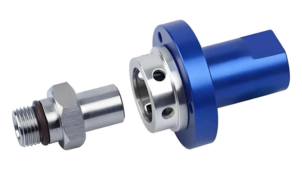
How to distinguish and select the connection threads of a rotary joint
The connection thread of a rotary joint (rotary union) is one of the most important specifications because it determines whether the joint can be installed correctly, sealed reliably, and operate safely under pressure and speed. The correct thread selection depends on thread standard, size, direction, medium, and installation method.
1. Identify the thread standard
Common rotary joint thread types include:
| Thread type | Full name | Common applications | Identification |
|---|---|---|---|
| NPT | National Pipe Thread (US standard) | Hydraulic, pneumatic, industrial equipment | Tapered thread, sealing usually with thread sealant |
| BSPT (R) | British Standard Pipe Taper | Europe, Asia industrial equipment | Tapered thread, similar appearance to NPT but different angle |
| BSPP (G) | British Standard Pipe Parallel | Hydraulic systems, rotary unions | Parallel thread, requires O-ring/gasket sealing |
| Metric thread (M) | ISO metric thread | European/Asian machinery | Measured in mm (e.g., M18×1.5) |
| UNF/UNC | Unified thread | North American machinery | Inch-based thread |
Key differences
NPT vs BSPT
- Both are tapered pipe threads.
- They are not interchangeable.
- NPT thread angle: 60°
- BSPT thread angle: 55°
- Even if they appear to fit, leakage may occur.
BSPP (G) vs BSPT (R)
- G thread: straight/parallel thread
- R thread: tapered thread
- G thread normally seals with:
- O-ring
- sealing washer
- gasket
-
2. Measure the existing thread
If the thread specification is unknown:
Step 1: Measure outside diameter
Use a caliper to measure the male thread outside diameter.
Example:
Approx. diameter Possible size 10.3 mm 1/8″ pipe thread 13.7 mm 1/4″ pipe thread 17.1 mm 3/8″ pipe thread 21.3 mm 1/2″ pipe thread 26.7 mm 3/4″ pipe thread 33.4 mm 1″ pipe thread (Actual dimensions depend on thread standard.)
Step 2: Measure pitch
Use a thread gauge.
Examples:
- M18×1.5 → 18 mm diameter, 1.5 mm pitch
- G1/4 → 1/4 inch BSP parallel
- R1/2 → 1/2 inch BSP tapered
Step 3: Check thread angle
A thread gauge can distinguish:
- 60° → NPT / UN thread
- 55° → BSP thread
3. Select thread according to rotary joint application
Hydraulic oil rotary joint
Recommended:
- BSPP (G)
- NPT
- Metric
Consider:
- Pressure rating
- Leakage prevention
- Hose compatibility
Water rotary joint
Common choices:
- BSPP
- BSPT
- NPT
For high-speed operation:
- Prefer precision-machined BSPP + sealing ring designs.
Air rotary joint
Usually:
- G thread
- NPT
Important:
- Avoid leakage because air loss affects speed control.
Coolant rotary joint
Common in:
- CNC machines
- Spindles
Usually:
- Metric thread
- G thread
Example:
- M16×1.5
- M18×1.5
- G1/4
4. Consider the rotary joint installation position
Male thread connection
Example:
Rotary joint male thread → Machine port female threadAdvantages:
- Compact
- Easy installation
Female thread connection
Example:
Rotary joint female thread → Pipe/hose male threadAdvantages:
- Flexible piping arrangement
5. Check thread direction
Rotary joints may require:
Right-hand thread (RH)
Most common.
Left-hand thread (LH)
Used when rotation direction could loosen a normal thread.
Example:
- High-speed rotating spindle
- Rotating shaft applications
Always confirm:
- Shaft rotation direction
- Manufacturer drawing specification
6. Use the manufacturer’s drawing whenever possible
For industrial rotary joints, the model number usually defines the thread.
Example:
1101-202-651 rotary joint
The correct connection thread should be confirmed from:
- Product drawing
- Installation manual
- Thread designation on the specification sheet
Typical markings:
- G1/4
- R1/4
- NPT1/4
- M18×1.5
Do not select only by diameter; the thread standard must match.
Quick selection procedure
- Check machine port thread standard
↓ - Confirm medium (water/oil/air/coolant)
↓ - Confirm pressure and speed requirements
↓ - Match thread type:
- US equipment → NPT often used
- European/Asian equipment → G/BSP or metric often used
- CNC spindle → metric/G commonly used
↓
- Verify sealing method and rotation direction
If you provide the rotary joint model number (for example 1101-202-651), manufacturer, and the port marking (such as G1/4, NPT1/4, M18×1.5), I can help identify the exact connection thread and replacement specification.